Monday, October 05, 2015

Gear profile generator

Having been inspired by the gear generator found at woodgears.ca I decided to have a go at doing this myself.

Some time ago, I had tried to do this in Java as a learning exercise. I only got so far and gave up before I managed to generate any involute curves required for the tooth profile. Trying to learn Java and the math required at the same time was probably too much and it got put aside.

Recently I had a look at the Go programming language. Then Matthias Wandel produced the page mentioned above, and I decided to have another crack at drawing gears.

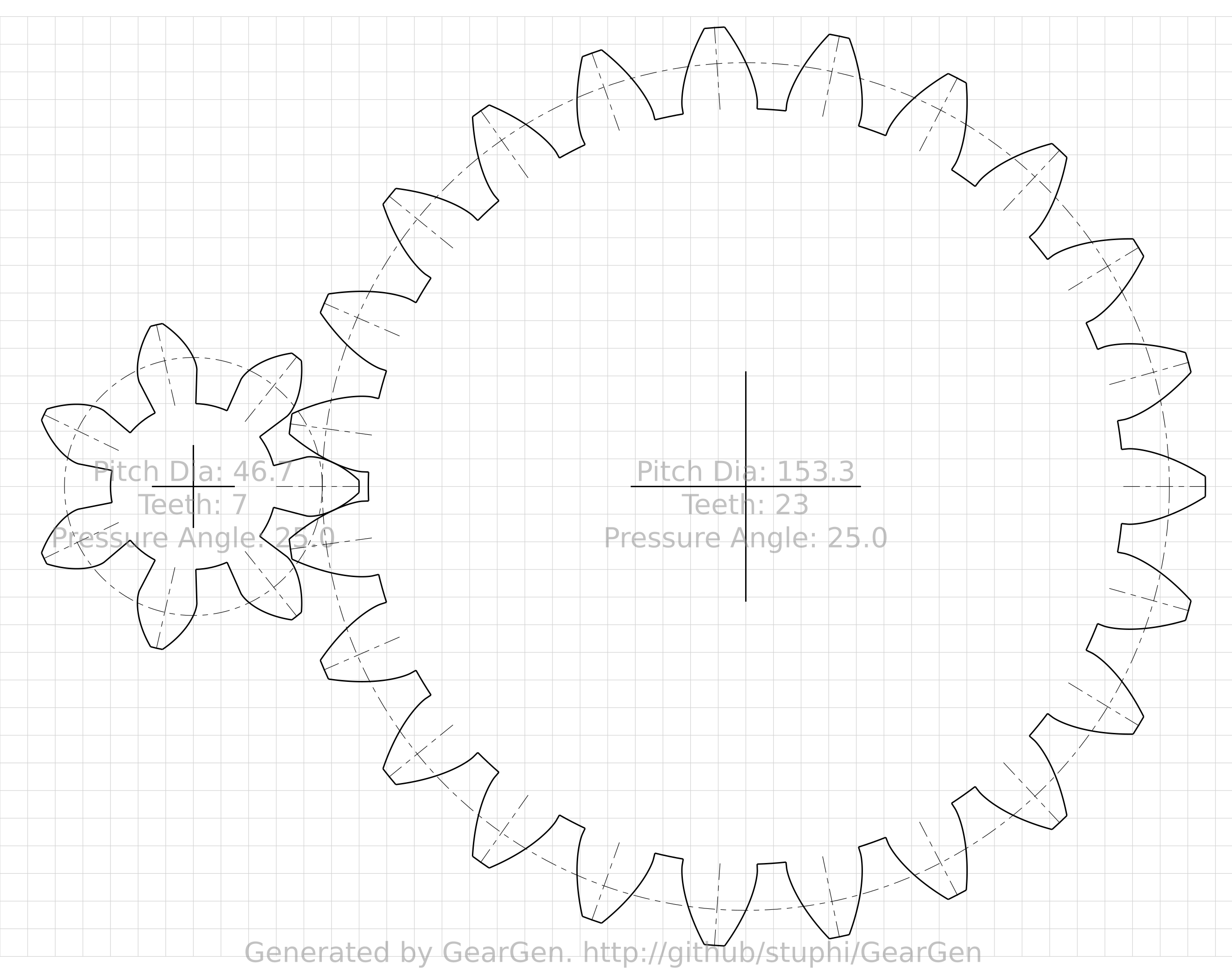
The results so far can be seen on Github, and an example is shown here.

Gear Profile Example Image

What I have learnt

  • Math makes my head hurt.
  • The Go programming language fits the way my brain works better than most other languages. I much prefer it to Java, and will try and see if I can tackle other problems with it, just for fun.

Saturday, April 11, 2015

DIY USB OTG Cable

Suddenly decided that I needed a USB OTG cable. Rather than wait for one in the post, i decided to make one from spare cables found in my box of bits.
Initially I thought that it would be a simple case of just cutting the cables and reconnecting a USB connector from a phone lead to a female USB socket. Unfortunately that is not the case.
The USB cable has four wires, but the micro USB plug has five contacts. The unused contact needs to connected to ground to make the OTG cable. The plug on the cable I used does not have a connection for the  extra pin, so I needed to rip it apart and blob a lump of solder on two pins. The body of the plug has a wall between each pin, so I rammed a small screwdriver in there to allow the soldered pins to fit.


I then reassembled the plug, and continued with the connecting the wires together. This was an easy case of , red to red, black to black, green to green and white to white. A piece of heat shrink covers the mess.
Now to use it. It allows me to plug a keyboard into my Nexus tablet. If I plug a mouse in, a pointer pops up. All of a sudden using the tablet feels like using a real computer. I am typing this with a keyboard on my lap down the garden with my tablet.
The real motivation for the cable was to allow me to use my phone to adjust the settings on my MultiWii based control board of my Quadcopter. For that, it seems even better than MultiWiiConf, and certainly a lot more convenient when out flying.

Thursday, January 29, 2015

Arduino and NRF24L01 for Quad-copter build

As part of my Quadcopter build, I am using a couple of Arduino's along with some cheap NRF24L01 from Banggood for the radio transmitter and reciever. The idea came from watching the YouTube channel iforce2d.

When I started developing (copying) the code for the NRF modules, I did a quick search for the required library. For no good reason, I opted for the RadioHead version. Part of my thinking was by using a different library from iforce2d, I would have to poke around in the code a bit more and lean something.

All went well with the initial trials. I managed to get the two modules talking to each other, and even had a simple processing script show the stick outputs by reading from the serial port of the receiver.

Things did not look so good when I plugged the flight controller in. For that I am using an Afro Mini32. With that connected to the computer and Baseflight running, the receiver tab showed a lot of fluctuations on the control signals.

Lots of poking , thinking, and even taking it into work to connect to an oscilloscope, it looked like the radio was mucking up with the timing of the PWM signal for the flight controller. Finally, I decided to give an alternative NRF library a try, and from the Arduino playground site, I selected this one. As per iforce2d, I think.

Well that fixed it. Although, at the same time I cleaned up my code and pulled lots debugging stuff out and changed one if loop to a while loop, so there is a chance that changing the Library was not the answer. Anyhow, it works well now. Just need some more bits to turn up and I can start on the actual copter!
Monday, January 19, 2015

Quad-copter Build Log - Part 2

Working Transmitter

After a bit of fiddling, the transmitter works. I have not tested it for range, other than making sure it works across the length of the house. At the moment it only has the standard NRF24L01 module. Although the high-power module has turned up, the antenna for it is still in transit.

As there is still no Quad copter to control, most of the testing has been done by watching numbers scroll up the screen from reading the serial output from the receiver. As this was getting painful, a simple processing script was written to display the control positions on the screen. 

Almost as soon as I started this, I wondered if it would be possible to get the processing script to pass the stick controls onto a flight simulator. A quick look at FlightGear turned into a quick flight around L.A. That is a project for another day.

Flight Control Board

A flight control board has been ordered. I decided on the AfroMini32. This has the usual accelerometers, gyroscopes and a barometer. It also uses a 32 bit micro controller so should be a capable piece of kit. Hopefully it will all come together by the summer.

Monday, January 05, 2015

Quad-copter Build Log

Having enjoyed watching a series of videos on YouTube, I have been inspired to have a go at building a quad copter. I hope to include here some notes that will act as a reminder for myself. If anybody else decides to try this, please don't rely on this information alone, but please do your research.

Radio

This seems like a good place to start. If this bit can't be made to work, then nothing has been wasted on motors, batteries ESC's etc.

Rather than build an entire transmitter, an old DigiFleet transmitter will be gutted and used for the housing, control sticks, knobs and switches.
I had been hanging onto this transmitter, thinking that I would use it someday, but in the meantime, the NiCAD cells had spilt their guts and pretty much wrecked the circuit boards inside. So nothing was lost by tossing out the control boards, to make space for an Arduino. At the same time, all the parts were removed to give everything a good clean.

Some parts were ordered from Banggood to get started on the radio. An Arduino Pro Mini to use as the reciever, and Arduino Leonardo for the transmitter, and a couple of NRF24L01 boards for the 2.4GHz radio link.

Connecting Arduino to NRF24L01 Boards

After receiving the Arduino boards, the first thing was to load new Blink programs. This confirmed that they worked, and I could program them. The only issue was for some reason the Leonardo will only work as root. When it cam to connecting the the NRF modules to the Arduino, it was again the Leonardo that was proved to be more challenging. In addition to the power lines, the NRF's require five extra connections. Three of those connections are not available on the standard header, but are available on the ICSP header. As the remaining two connections can be assigned to any digital pin, it is possible to have all of the Leornardo's 12 analogue input pins free to use. This would make it possible to connect up all the controls on the radio, if needed.

The diagram below shows how the NRF boards were connected for initial testing.

With this set-up, it has been possible to communicate between the boards from different locations in the house.

Software

The YouTube videos that started this mentioned a specific library for the RF modules. For no good reason, for this test, the Radio Head library has been used.

Learnt so far

  • Getting the radios to work was easy.
  • The Leonardo is not quite as simple to use as the pro-mini. Mainly due to the build in USB has to be handled by the Arduino software in a different way.
  • Choosing the Leonardo for the transmitter will allow me to use all 12 analogue inputs.
  • Just because a NRF24L01 board has a plug for an aerial does not mean that it is the high power version!